Visualization Engine Guide for Beta Testers
Before You Begin the Visualization Engine Beta
- The SurfaceTypes.sceneryTemplate file needs to be downloaded and copied to the ‘Export Templates’ folder in your AppData folder:
AppData\Roaming\Transoft Solutions\Visualization Engine\Export Templates. - Download and open the Sample Surface Types drawing file.
Objective
This document is to help AutoTURN Pro customers evaluate an exciting new approach to visualizing your swept path studies. Users can now create advanced animations to support their presentations to the public and clients with an AutoTURN Pro simulation. This feature is currently in the beta phase; hence we welcome early customer feedback. Any comments or suggestions can be sent to support@transoftsolutions.com with the title stating: “Visualization Engine Beta”. To get the most out of this feature, we have prepared the following guide so that there is a minimal learning curve where users can utilize this feature to its fullness.
Procedure
There are three main checkpoints that we have to follow in order for this Visualization tool to be utilized to its full potential. They are the following:
- Settings
- Prepare Scene
- Generate Visualization
Each of the 3 steps is particularly important and they each have their own workflow. Please take some time to read through this guide so that a stunning picture can be painted with your AutoTURN Pro simulation.
1. Settings – Units
It is paramount that the unit settings match within the CAD platform and AutoTURN Pro. This is because the Visualization Engine parameters reference the unit setting to achieve the correct scaling between the scene and simulation.(See screenshot below.)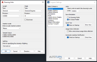
Fig. 1 – Drawing units must match the simulation units.
2. Prepare Scene
The majority of the magic happens here in this step where the workflow prompts the user to prepare what is to be displayed (like a movie scene). This tool allows you to select the geometric elements/objects in your drawing and assign the layers/levels containing those objects to selected surface types for visual enhancement. Once the allocation of the layers/level has been completed, AutoTURN Pro can save your settings as a Scene to be used again.
Two main ideas here within this step:
- Each layer/level is assigned to a surface type.
- Each surface type displays a unique output for a remarkable display.

Fig. 2.1 – Different surface types
Fig. 2.1 shows the surface types included in this Beta version. Each will be explained in more detail below.
2.1 How to arrange layers/levels within CAD and how to assign them to a surface type?
Each of the layers/levels will be displayed in the “Edit layer template”, described in more detail in section 2.4, and where users can assign a surface type to each of the layers/levels in the drawing.
In a complex drawing with multiple layers/levels, the user will need to map a particular surface type to the desired layers/levels. This will require an initial setup, but once the mapping is done, this can be saved as a template that can be reused again. This can be simplified further if your team uses a consistent layer/level naming convention. The saved template can be used for any other drawings. Please note that you do not necessarily need to assign a surface type to all layers in the drawing, only those that you need to render in your visualization. See sections 2.3 and 2.4.
2.2 What are some of the outputs of the surface types?
Below are the surface types from Fig 2.1 and their respective output and features (which cannot be changed).
(a) Paved Area
- Within a closed polyline or hatch area, this surface type is intended to represent a concrete or asphalt surface. The displayed color is set as dark gray to illustrate a road or paved surface.

(b) Generic Area
- Within a closed polyline or hatch area, this surface type is intended to represent a sidewalk or other dedicated area. The displayed color is set as light gray.

(c) Grass Area
- Within a closed polyline or hatch area, this surface type is set as light green where the area is intended for grass area, sidewalk buffer, or landscape area.

(d) Tree Area
- Within a closed polyline or hatch area, the visualization engine will randomly scatter trees into the defined area. This lessens the amount of 3D work required and reduces the drawing file size making it easier to share your model with clients or involved parties.
- The size of the trees is randomized by the visualization engine.
- When “Wind” is enabled in the pop-up visualization window, users will observe the effect of the wind on the trees.

(e) Building Area
- With a closed polyline or hatch representing the outline of a building, the visualization engine will assign a white surface type and extrude the boundary to the height specified in “Edit layer Template” dialog. (See Fig. 2.2). Curves and splines will be simplified and represented by extruded linear segments.

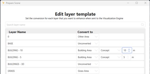
Fig. 2.2 – Building height assigned to the different layers/levels
(f) Other Area
- Within a closed polyline or hatch area, this area references the layer/level color assigned within the CAD platform. If the color for the layer/level is blue, the visualization engine will output the blue that was chosen within the CAD platform. For example, users can use this for bodies of water like ponds in blue or marking a dedicated bicycle parking area in yellow.

2.3 What elements in the drawing can be imported:
- Closed Polylines
- The polylines must be manually inputted as a “closed” polyline. If a polyline looks to closed, because the start and end vertex is coincident, but has not been defined by the user as closed, the visualization engine will not be able to determine this as an area. Close this as a boundary and it will be detected by the visualization engine.
- Geometry: circle, rectangle, etc.
- These work the same as closed polylines.
- Hatch area
- Hatch areas will work the same as closed polylines but when converted the hatch pattern will be replaced with a solid fill based on the surface type defined for the layer/level.
- 3D elements
- 3D elements in the drawing will come through into the Visualisation Engine as drawn, so the layer/level should be set to “unconverted”.
- Lines or arcs and lineweight
- Cannot be read by the Visualization Engine.
- Blocks/Cells
- The elements within a block/cell will treated as individual items, and will only show as filled if they comprise of 3D elements, and hatches. Closed Polylines within blocks are not currently supported.
- Surface types assigned to layers/levels within a block are currently ignored by the Visualization Engine
2.4 Should “All Objects in Drawing” be used all the time?
If you have AutoTURN 3D simulations already created within the drawing, these 3D simulations will show as part of the scene, where a vehicle will always be stationary at the location of the beginning and end of the simulation.
It is recommended to select “All Objects in drawing” only when the drawing is not overly complex, covers a relatively small area, and where there are no 3D simulations already created within the drawing. Otherwise, use “Select from CAD” where you have more control over what items will be converted or transferred into the Visualization Engine.

Fig. 2.4 – Options to select Geometry
2.5 Here are some items that are worth noting when preparing the scene:
- Transparencies and materials defined in the CAD platform are not supported.
- Extrusions can be imported, but the effects of lighting and shading can’t be controlled.
3. Generate Visualization
Once the Prepare Scene is done, the next step would be to generate the visualization. Select the 3D simulation that has been created. Users can choose multiple 3D simulations.
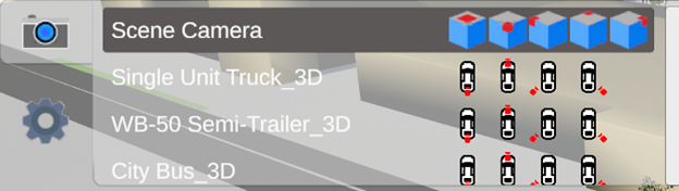
The visualization engine will pop up in a separate window (not within the CAD platform). From within this window, the user can orbit or pan similarly in a CAD environment. There are other design features that this visualization offers such as the ability to view the environment via the driver’s eye. Users can switch to that using the “Camera” option within the visualization window.
The visualization engine will appear in a separate window, and not within the CAD platform. Within this window, the user can orbit or pan, similar to working in the CAD environment, or by using the side panel navigation tools for pan, orbit, and look.
![]()
A unique design feature of the visualization engine is the ability to view the environment via the driver’s eye or a follow-mode on the vehicle simulation and to quickly switch between these views at any time, including when playing back the animation. Users can switch to these views using the “Camera” option within the visualization window. Viewing from the driver’s eye would allow the designer to focus on what road furniture can be seen before the site is built/retrofitted.
There is also a timeline at the bottom of the window where the user can play the animation or move to a point in time along the simulation.
Conclusion
This guide is to help users to test out the new AutoTURN Pro Visualization tool.
Any feedback or suggestion is welcomed and can be sent to [email protected] with the subject of the email labeling: “Visualization Engine Beta”.
If more details of this feature are needed, users can visit the help file on Prepare Scene and Generate Visualization.